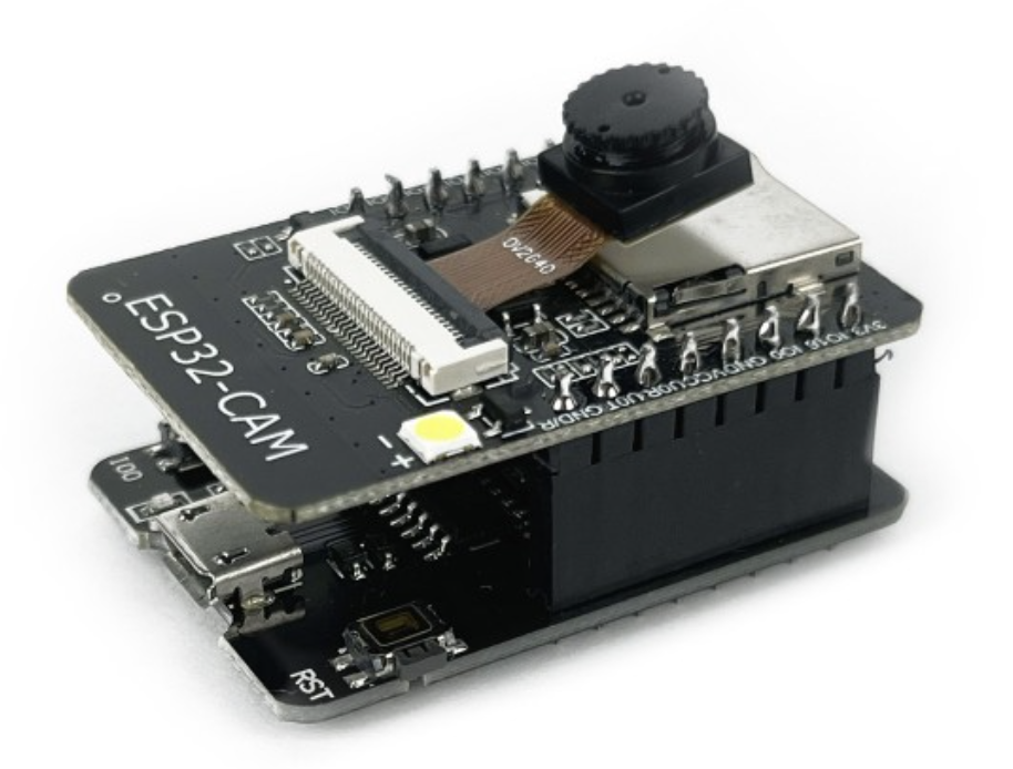
To build my own security system I am using as hardware:
- ESP32-CAM: R$78.00 brazilian reais, around 14.35 USD.
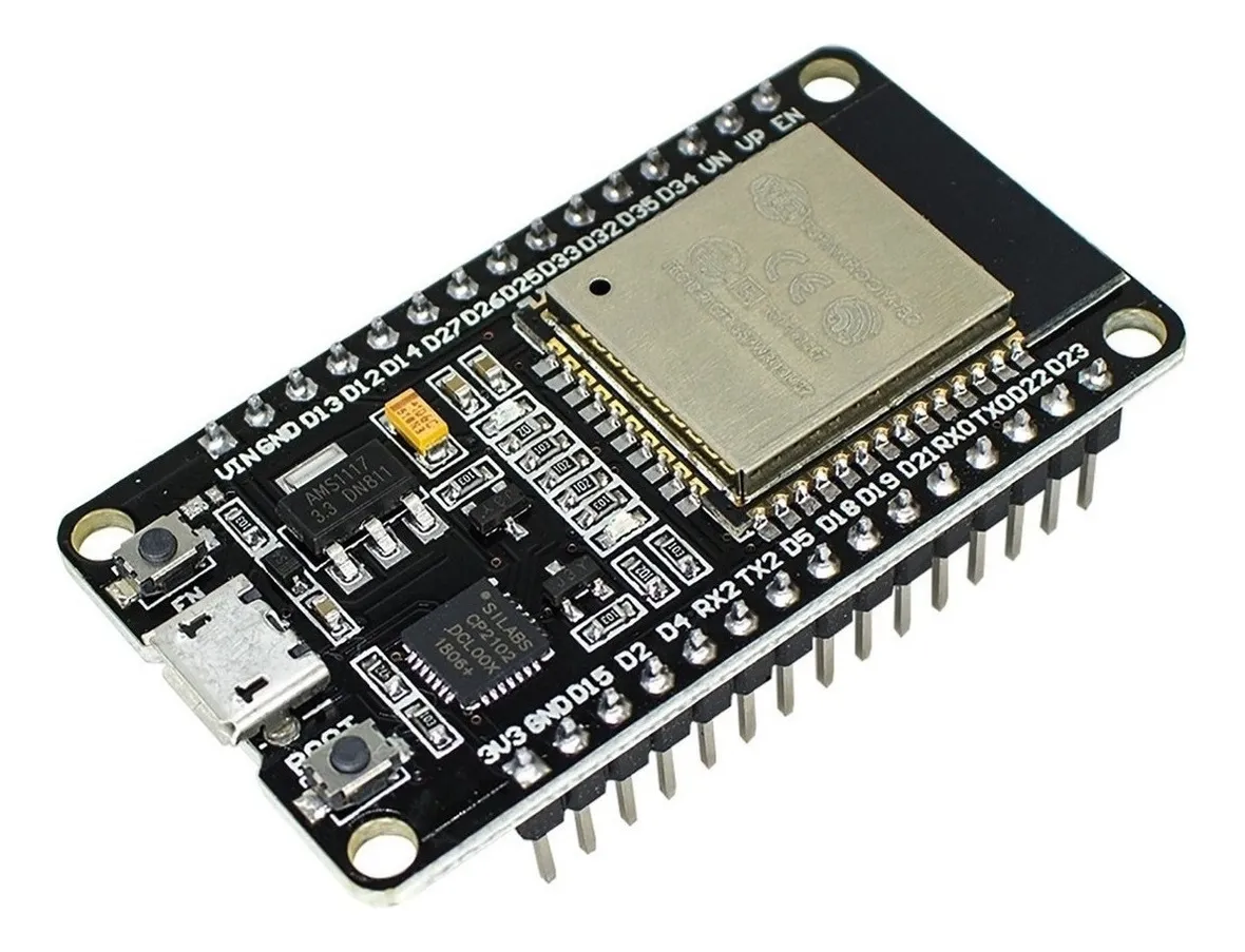
- ESP32 WiFi: R$40.00, around 7.36 USD.
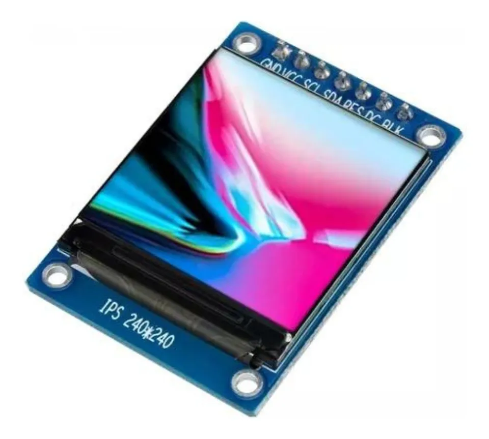
- TFT Display: R$50.00, around 9 USD.
The software I am using are:
- HTTP server written in Go
- Python for AI processes
The idea is to install the ESP32-CAM at some spot in my house that allows me to see outside.
The ESP32-CAM is connected to my house WiFi.
I altered the default image quality and size to stream a 640x480 image.
The Go sever will be my main form of connection to the camera feed. Because the ESP32-CAM cannot handle well multiple connections I decided to make a Go server that will stay connected to the camera feeds and keep the last frame on memory. This will allow me to fetch the image from the ESP32-CAM only once and feed it to as many connections as I need through the go server. This server will have 4 main endpoints:
/stream- opens a connection to keep feeding the client with the latest frame from the ESP32-CAM/capture- serves the last frame/b64capture- same as/capturebut encodes to base64 before serving the frame/streamai- the same as/streamwith the difference that the image fed has been processed by a YOLO model for object detection/aicapture- the same as/capturebut with the image processed by AI/aiupload- endpoint for uploading images with the predicted bounding boxes
The AI model will run in a python script. I found easier to use python as it has more support for different models and is easier to use them.
The script will keep making requests to /capture, processing the imagem, drawing the bounding boxes around the detected objects and uploading the new image to another endpoint.
The uploaded image will be the one served on /aicapture and /streamai.
The model I am currently using is a YOLO-v4-tiny that I found the weights in github. It is super easy to use with opencv2 and has good perfomance and speed.
NOTE: All the code is available here
Setting up the ESP32-CAM
I mostly follow this guide to prepare the ESP32-CAM Web Server. It has all the information needed to connect the pins correctly and upload the code via the Arduino-IDE. Notice that if you use a programming board you do not need the FTDI board and can simply connect the ESP32-CAM to the computer using a micro-usb cable, like I did.

The code for the server can be found in the examples for the ESP32-CAM in the Arduino-IDE, however I made a few changes. I removed any unnecessary conditional and information in the code. I also changed the default quality and framesize to 6 and 640x480, respectively. Because I might deploy in different places, that have different WiFi, I creadted a function that would test both WiFi and keep connected to the one with the strongest signal.
Here is the main code for the ESP32-CAM Web Server:
#include "esp_camera.h"
#define CAMERA_MODEL_AI_THINKER // Has PSRAM
#include "camera_pins.h"
#include "wifi.h"

void startCameraServer();
void setupLedFlash(int pin);

void setup() {
  Serial.begin(115200);
  Serial.setDebugOutput(true);
  Serial.println();

  camera_config_t config;
  config.ledc_channel = LEDC_CHANNEL_0;
  config.ledc_timer = LEDC_TIMER_0;
  config.pin_d0 = Y2_GPIO_NUM;
  config.pin_d1 = Y3_GPIO_NUM;
  config.pin_d2 = Y4_GPIO_NUM;
  config.pin_d3 = Y5_GPIO_NUM;
  config.pin_d4 = Y6_GPIO_NUM;
  config.pin_d5 = Y7_GPIO_NUM;
  config.pin_d6 = Y8_GPIO_NUM;
  config.pin_d7 = Y9_GPIO_NUM;
  config.pin_xclk = XCLK_GPIO_NUM;
  config.pin_pclk = PCLK_GPIO_NUM;
  config.pin_vsync = VSYNC_GPIO_NUM;
  config.pin_href = HREF_GPIO_NUM;
  config.pin_sccb_sda = SIOD_GPIO_NUM;
  config.pin_sccb_scl = SIOC_GPIO_NUM;
  config.pin_pwdn = PWDN_GPIO_NUM;
  config.pin_reset = RESET_GPIO_NUM;
  config.xclk_freq_hz = 20000000;
  config.frame_size = FRAMESIZE_VGA;
  config.pixel_format = PIXFORMAT_JPEG;  // for streaming
  config.grab_mode = CAMERA_GRAB_WHEN_EMPTY;
  config.fb_location = CAMERA_FB_IN_PSRAM;
  config.jpeg_quality = 6;
  config.fb_count = 1;

  // camera init
  esp_err_t err = esp_camera_init(&config);
  if (err != ESP_OK) {
    Serial.printf("Camera init failed with error 0x%x", err);
    return;
  }

  sensor_t *s = esp_camera_sensor_get();

// Setup LED FLash if LED pin is defined in camera_pins.h
#if defined(LED_GPIO_NUM)
  setupLedFlash(LED_GPIO_NUM);
#endif

  connectToStrongestWiFi();

  startCameraServer();

  Serial.print("Camera Ready! Use 'http://");
  Serial.print(WiFi.localIP());
  Serial.println("' to connect");
}

void loop() {
  delay(100000);
}
NOTE: The code for the camera server can be found here.
Setting up the HTTP server in Go
Because I had troubles opening multiple connections to the ESP32-CAM Web Server, probably because it can not handle much since its already video streaming, I decided to create a server using Golang.
This server is responsible for connecting to the video streaming and keep the current frame in buffer, any client connecting to it will receive the current frame captured from the camera, this allows a single connection to the ESP32-CAM, but it does not limit the number of clients that can receive the video streaming.
The idea for the future is to have more micro-controllers connected to this server that can receive and send requests, so that I can control multiple micro-controllers from a single application.
A go coroutine runs in the background as soon as the applications is initiated, this is responsible for updating the current frame taken from the camera. The endpoints that serves the images directly are:
/stream/capture/b64capture
We will also allow upload of frames that were processed by AI. This is done through the endpoint /aiupload. This endpoints expects an image that has bounding box drawn into it and a header that will inform if a person was detected in this image or not.
The frames received by /aiupload are then served via these endpoints:
/aicapture/streamai
The /aicapture endpoints also sends in its header if the there was a person detected in the current frame. The main function for the server is:
func main() {
  cfg := config.ReadConfig()

  go keepSavingFrame(cfg)
  go capture.FetchFrameLoop(cfg, &mu, &frame)

  http.HandleFunc("/aiupload", receiveAIFrame)
  http.HandleFunc("/capture", serveFrame)
  http.HandleFunc("/b64capture", serveB64Frame)
  http.HandleFunc("/aicapture", serveAIFrame)
  http.HandleFunc("/stream", streamHandler)
  http.HandleFunc(("/streamai"), streamAIHandler)

  http.ListenAndServe(":8090", nil)
}
The config is read from an YAML file that contains variables like the ESP32-CAM url. The keepSavingFrame function allows saving the last frame if a person was detected and the FetchFrameLoop is responsible for retrieving the newest frame from ESP32-CAM and saving it to the frame variable.
NOTE: The code for the HTTP server is here.
AI Process
After browsing around some models and methods to run a computer vision model, I haved decided to use yolov4-tiny with opencv in Python. I thought about using C++ or maybe even Go directly, but the setup was not as easy and I found that the chosen combination still provides good performance at a reasonable speed. I am processing 4 images per second, this felt enough for my purposes.
The main python script simply starts an infinite loops that keeps calling /b64capture endpoint to fetch the latest frame already encoded in base64, this made also easier to decode the image and feed to the model loaded with opencv. The model detects a number of classes, including person, dog, laptop and so on. Every detected class along with is bouding box will be shown in the image, however we only keep track of persons detected. The new image and the information of person detectition are sent to the /aiupload endpoint, then after a small interval we start the process again.
This separates the AI process from the main the server, allowing to run them in separate machines if needed and swapping the model without downsides to the server.
NOTE: The code for the AI process can be found here.
Deploying
With this in place we can already access images from the camera with or without AI predictions via our home network, simply by acessing the IP address in our browsings in our phones and notebooks. However I also wanted a small screen in my house that would be always connected to the server displaying the images.
In order to achieve this goal, I bought a TFT display:

This display is only 1.3 inches and fits an image of 240x240, so I need to do some resizing before displayin the image. However it easy to work with. It only needs 4 pins for reciving data and can be worked with using the TFT_eSPI and TJpg_Decoder libraries.
The second piece of hardware is an ESP32 board with WiFi:

This board is similar to the ESP32-CAM, with the difference being clear that it has no camera module and it supports more connections and has a micro-usb built-in. Together with a WiFi chip and 4MB of memory, it was a good choice for connecting to the HTTP server, retrieve the last frame and displaying it in the TFT display.
Here is the code:
#include "tft_setup.h"
#include "mywifi.h"
#include <HTTPClient.h>
#include <TJpg_Decoder.h>
#include <SPI.h>
#include <TFT_eSPI.h>

#include "NotoSansBold36.h"
#define AA_FONT_LARGE NotoSansBold36

TFT_eSPI tft = TFT_eSPI();

bool tftOutput(int16_t x,int16_t y,uint16_t w,uint16_t h,uint16_t *bmp){
  if (y >= tft.height()) return 0;
  tft.pushImage(x, y, w, h, bmp);
  return 1;
}

void setup(){
    // setup monitor and wifi ...
}

void loop(){
  HTTPClient http;
  http.begin(serverUrl);

  if (http.GET()==HTTP_CODE_OK){
    int len = http.getSize();
    auto *buf = (uint8_t*) heap_caps_malloc(len, MALLOC_CAP_INTERNAL|MALLOC_CAP_8BIT);
    http.getStreamPtr()->readBytes(buf,len);
    uint16_t w,h; TJpgDec.getJpgSize(&w,&h,buf,len);
    TJpgDec.drawJpg(0, 0, buf, len);
    free(buf);
  } else {
    tft.fillScreen(TFT_BLACK);
  }
  http.end();

  // Wait before drawing again
  delay(250);
}
NOTE: The complete code can be found here.